 |
| Add caption |
The stuffing box is mounted on a ring which is bolted onto the underside of the scavenge air box. The stuffing box is taken out together with the piston rod during overhaul of the piston, but also can be disassembled for inspection in the crankcase with the piston remaining in position.
The stuffing box housing is in two parts, assembled by a flanged joint. In the housing five ring grooves have been machined out of which the two uppermost ones accommodate sealing rings that prevent scavenge air from blowing down along the piston rod. In the lowermost grooves scraper rings are fitted which scrape the lubricating oil of the piston rod. The oil is led through bores in the housing and back to the crankcase.
Between the two uppermost ring grooves, for the sealing rings, and the three lowermost grooves, for the scraper rings, a cofferdam has been machined out which, through a bore in the housing and a connecting pipe, communicates with a control cock on the outside of the engine. It can be checked by opening this control cock that the scraper and sealing rings are functioning correctly.
Sealing ring section
Top ring The two sealing rings each consist of a four piece brass ring which accommodates eight brass sealing segments, two per base, guided by four cylindrical pins. The parts are pressed onto the piston rod by a helical garter spring.
Scrapper ring section
Bottom section ring The three scraper rings are made up of three steel base parts into which two lamellas are fitted into a grooves machined in each part. A garter spring keeps the ring in contact with the piston rod. Scraped off oil is led through ports in the base ring back to the sump.
assembly
A clearance is given at the ends of the parts to ensure contact with the piston rod as the rubbing face wears.
Author note:
Extremely high wear was noted on a class of vessels with B&W gfca engines. Balls of wire wool where removed from between the segments at overhaul.
Repair was to send the piston rods for machining from their cloverleaf shape back to circular. When fitting new lamellas emery paper was wrapped around the rod and the lamellas 'bedded' in. This prevented the segments from canting and the ends of the lamellas digging in.
I am the author of most of the work on your website against which you are making financial gain. If you do not gain permission or remove it I will take further action. My site is non-commercial, I note you have placed content from marinediesels.info which is a commercial site, you are in breach of his copyright and as such ne may not be as generous in allowing you time to remove his work before taking further action.
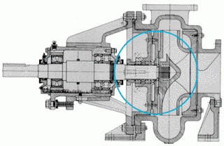
ReplyDeleteNote that you are mixed up between the stuffing box found on a slow speed engine and a gland box found on a pump
brian