Showing posts with label Lifting Operations. Show all posts

Thursday, 21 June 2012

Lifting

Lifting
Lifting
Lifting using Accessories

Calculation of Load

    There are only two types of load to be lifted
    • Known- there must be a Certificate of Weight or a Guaranteed Weight name plate attached.
    • Estimated- Any other weight. When doing lift calculations 50% must be added to estimated weight
    Note that in addition to the load itself additional factors such as ground effect e.g stiction and dynamic loading effects of lifting with relative motion between crane mount and load platform must be taken into account

Safe Working Loads

For a straight vertical lift the maximum lift weight is the Safe Working Load (SWL) of the lifting accessory
For a lift using an accessory with two legs or two matched pairs used at angles up to 45o from vertical ( i.e. non vertical to 90o included) then the maximum SWL is 1.4 (normally rounded up to 1.5) times the SWL in each leg e.g. the maximum lift for two matched 5 tonne strops is 7.4 tonnes

The maximum included angle is 90o, no lift should take place with angles greater than this.
For 3 or more piece lifting accessories of 3 or more identical lifting accessories used at angles up to 45o from vertical then the maximum Lift is 2.1 times the SWL or each leg. e.g the maximum lift weight of four matched 5 tonne strops is 10.5 tonnes

The maximum included angle is 90o

Note

    • For lifting accessories such as Multileg chain slings (�Brothers�), the SWL takes in to account that may be used at angles up to 45o and therefore the maximum lift weight would be the SWL of each leg times the number of legs ( or stated Total Lift) although this should be clear stated on Test Certificate.
    • The reduction in capability also applies to Shackles used when used in non vertical Lifts ( Dee Shackles must only be used in vertical lifts)
    • The reduction in capability also applies to Chain blocks, lever hoists which are in use.
    • For non uniform shaped loads special consideration has to be given to the Centre of Gravity and possible localised overloading.

Lifting- slinging

Lifting- slinging
Add caption
when taking a course as a'designated person for lifting operations I was horrified to reaise just how dngerous some of the operations I had been carrying out. This page demonstrates the lifting factors that you should be applying to lifting accessories

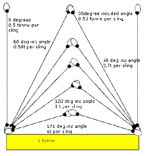
Sling Angles

The abve shows the loading in slings depending on the included angle. It can be seen that fitting too short a pair of slings and thereby creating too great an included angle can substantially increase the loading in the sling and cause it to fail
You should not consider any lifting operation with an included angle greater than 90 degrees and then you should give a 1.5 factor for the slings i.e. the slings should be at least 0.75 tonne each to lift the 1 tonne weight

Choking

This effect also occurs when choking a sling
Should the choke be batterned down it is possible to generate very high included angles severely straining the sling in this area and can easily lead to failure. Should it be necessary to put a wrap on a lift for security then you always consider making 2 full turns. If this is not possible then the included angle should never be reduced below 90 degrees and a 1.5 factor should be applied to the sling.

Inspection Criteria

Eyebolt(Dynamo)

Check Code and SWL legible
Ensure valid test certificate
Check Threads for wear and distortion
Ensure minimum 1.5 threads remaining when pin home
Ensure wear less than 8%
Ensure no nicks, cracks or distortions
Remove corrosion and treat as wear
Ensure no indication of heat damage or weld splatter

Eyebolt(Shoulder)

Check Code and SWL legible
Ensure valid test certificate
Check Threads for wear and distortion
Ensure minimum 1.5 threads remaining when pin home
Ensure wear less than 8%
Ensure no nicks, cracks or distortions
Remove corrosion and treat as wear
Ensure no indication of heat damage or weld splatter

Shackle (Dee)

Check Code and SWL legible
Ensure valid test certificate
Check Threads for wear
Ensure Pin correct for body, of the same material
Ensure pin head shoulder is well seated
Ensure minimum 1.5 threads remaining when pin home
Ensure wear less than 8%
Ensure no nicks, cracks or distortions
Check shackle not opening up
Remove corrosion and treat as wear
Ensure no indication of heat damage or weld splatter

Shackle (Bow)

Check Code and SWL legible
Ensure vald test certificate
Check Threads for wear
Ensure Pin correct for body, of the same material
Ensure pin head shoulder is well seated
Ensure minimum 1.5 threads remaining when pin home
Ensure wear less than 8%
Ensure no nicks, cracks or distortions
Check shackle not opening up
Remove corrosion and treat as wear
Ensure no indication of heat damage or weld splatter

Masterlink

Check Code and SWL legible
Ensure valid test certificate
Ensure wear less than 8%
Ensure no nicks, cracks or distortions
Remove corrosion and treat as wear
Ensure no indication of heat damage or weld splatter

Padeye

Check Code and SWL legible
Ensure valid test certificate
Ensure wear less than 8%
Ensure no nicks, cracks or distortions
Remove corrosion and treat as wear
Remove paint and NDT test weld as required
Ensure no indication of heat damage or weld splatter

Sling(Chain)

Check Code and SWL legible
Ensure valid test certificate
Ensure wear less than 8%
Ensure stretch less than 5%
Ensure Turn or twist a maximum 1/2 turn in 4 metres (hanging)
Ensure no nicks, cracks or distortions
Remove corrosion and treat as wear
Ensure no indication of heat damage or weld splatter
Ensure hooks are of the 'C' design or fitted with safety hook
Ensure hook end is in align with shank
Ensure hook throat opening has not increased by 15%
Ensure hook throat shank wear less than 10%
Ensure Clutch in good condition

Sling(Wire)

Check Code and SWL legible
Ensure valid test certificate
Ensure diameter consistent over length
Ensure no more than 5% randomly broken wires in 10 rope diameters
Ensure no more than 3 wires broken in local group in any one strand or 6 rope diameters
Check external wear less than 10 & of nominal
Remove corrosion and treat as wear
Check for excessive waviness
Check for strand protrusion
Check for core protrusion
Check for localised increase in core diameter due to core deterioration
Check for localised reduction in diameter
Check for memory kinks
Check for flatterned portions
Check integrity of eyes and fittings
Check for heat distortion
Check for pitting and prescence of weld splatter

Sling(Web)

Check Code and SWL legible
Ensure valid certificate of compliance
Check scuffing damage not excessive
Check for chemical/contaminants damage
Check for selvedge damage
Check non load bearing outer sheaf of Round slings not broached
Check for Heat and friction damage
Check integrity of eyes and fittings
Ensure less than 8 lines in 25mm damaged stitching
Check for pitting and prescence of weld splatter

Sling(Multileg)

Check Code and SWL legible
Ensure vald test certificate
Ensure wear less than 8%
Ensure stretch less than 5%
Ensure Turn or twist a maximum 1/2 turn in 4 metres (hanging)
Ensure no nicks, cracks or distortions
Remove corrosion and treat as wear
Ensure no indication of heat damage or weld splatter
Ensure hooks are of the 'C' deisgn or fitted with safety hook
Ensure hook end is in align with shank
Ensure hook throat opening has not increased by 15%
Ensure hook throat shank wear less than 10%
Ensure Legs are of the same length
Ensure Clutch in good condition

Chain Block

Check Code and SWL legible
Ensure valid test certificate
Degrease, disassemble and clean for inspection
Ensure load Chain has wear less than 8%
Ensure load Chain has stretch less than 5%
Ensure load Chain has Turn or twist a maximum 1/2 turn in 4 metres (hanging)
Ensure load Chain has no nicks, cracks or distortions
Remove corrosion and treat as wear
Ensure load Chain has no indication of heat damage or weld splatter
Ensure hooks are of the 'C' design or fitted with safety hook
Ensure hook end is in align with shank
Ensure Gears in good condition
Check chain attachements and Clevis pins
Check bearings, pins rollers for distortion and wear
Check pawl and ratchet for work and operation
Ensure hook throat opening has not increased by 15%
Ensure hook throat shank wear less than 10%

Lever Hoist

Check Code and SWL legible
Ensure valid test certificate
Degrease, disassemble and clean for inspection
Ensure load Chain has wear less than 8%
Ensure load Chain has stretch less than 5%
Ensure load Chain has Turn or twist a maximum 1/2 turn in 4 metres (hanging)
Ensure load Chain has no nicks, cracks or distortions
Remove corrosion and treat as wear
Ensure load Chain has no indication of heat damage or weld splatter
Ensure hooks are of the 'C' design or fitted with safety hook
Ensure hook end is in align with shank
Ensure Gears in good condition
Check chain attachements and Clevis pins
Check bearings, pins rollers for distortion and wear
Check pawl and ratchet for work and operation
Ensure hook throat opening has not increased by 15%
Ensure hook throat shank wear less than 10%

Beam

Check Code and SWL legible
Ensure valid test certificate
Check condition as required

Other

Check Code and SWL legible
Ensure valid test certificate
Check condition as required

Lifting Operations in ship

 Lifting Operations in ship
Lifting Operations in ship
The following contains subjective comment on lifting operations with the Grove AT1500, telescoping crane with flyboom It does not constitute a set of instructions and does not supersede in any way LOLER of other lifting operation regulations. In addition there are several factors such as outrigger extension, outrigger pad size and ground state which have been specifically excluded as they apply only to a shore based lift. We assume that the counterbalance weight is fixed and that the stability area of the load capability chart does not apply
In addition not considered here is the trim of the vessel although this will have an effect and should be considered

Crane Mounted Load Computer

The Grove Crane has a load computer which measures the load weight, Boom Extension and Boom angle. Form this it can compare computed load against a model stored within its memory. As the load approaches overload alarms are sounded. The computer has an extra mode which takes into account operation with the flyboom. This load computer is there as a safety factor and in no way should be considered to replace proper planning.

Lifting operations.

    To carry out a safe lifting operation a set of variables must be known; these consist of the following
      The weight of the lift.
    • The height of the lift
    • The Radius of the lift
    • Obstructions within the lift area
    • The Sea State

Weight Of lift

This may be either a known weight i.e. a weight which is certified and clearly marked, or an unknown estimated weight- in which case the weight is estimated and a factor of safety applied
    To be added to the lift weight is the weight of the hook and lifting accessories before calculations are carried out. For the hook this is given as a test weight of
    • 0.20 tonne for 10t hook and headache ball
    • 0.65 tonne for 50t 3 sheave block
Note that unless the lift weight is certified it is always classed as estimated in all circumstances.

Height of the Lift.


Note this is measured form the boom pivot point and not the deck. The height of the pivot point above the deck is 4.2m

Radius of Lift

In a similar fashion the radius is measured from the pivot point and not the centreline of the crane. The distance from the pivot to the centreline is 2.1m

Obstructions within lift area

The area not only where the load will be lifted and put down, but also the area covered whilst the crane is slewing. Should this be of particular concern a lifting plan should be created and discussed with the crane driver highlighting areas of concern and how best the Crane drive may avoid them. It should be understood that the crane driver may be unsighted of some of these obstructions therefore where this is considered to be a high risk a lift supervisor should be designated to guide the crane driver at all times. Special consideration has to be given to lifts of unusual shape or where spreader bars are in use.

The Sea State

Vessel lift operations differ from shore based operations in that dynamic load forces have to be taken into consideration. The worst sea state condition considered to occur during the whole operation should be used and lift calculations based on that The Dynamic Loading factor stated in QGPS Lifting Equipment Regulations is 2.4 times for routine loading/unloading. A factor of 1.35 may be applied after written consent. maximum wind speed is given as 25knots and maximum wave height of 2m

Lifting tackle Inspections

A lifting tackle inspection by a competent person is required on all lifting accessories every 6 months. However, it is also required that all lifting accessories are examined for defects before use and this includes all crane operations. Appendix C gives a listing of the failure parameters applicable to typical lifting accessories

Worked Example

A load of estimated weight 3 tonne is to be lifted from a platform at a level of 20m above sea level. The vessel can manoeuvre so that the base of the centreline of the crane is within 20m of the lift. The sea state is calm

Lift Weight

The weight is a estimated 3tonne lift with a 100% factor of safety this gives a weight of 6 tonne for calculation. The 10 tonne block is fitted adding 0.2 tonne. The lifting accessories are estimated at 0.1 tonne. This gives a total weight to lift of 6.4 tonne

Lift Height

The height of the lift above sea level is 20m. The freeboard is 1.5m and the crane pivot is 4.1m above the deck This gives a lift height of 14.4m

Lift radius

The Lift is 20m from the centre line. The pivot is 2.1m behind the radius therefore the lift radius becomes 22.1m

Obstructions

The lift is clear of obstructions. However to clear the lift and ensure that the accessories are properly placed the Gib head has to be 2m above the lift. This changes the height of the boom to 16.4m

Calculation of Boom extension

The easiest way to do the following is with graph paper with suitable scaling

however it is possible to calculate the required boom length.

Checking the Cranes Capability

We now look at the Lifting capacity chart for the crane

. Here we can see that at 20m radius/28.04m boom extension the lift capability is 11.9 tonne. For a 22m radius with same boom extension the lift capability is 10.5 tonne. As are lift is 6.4 tonne the crane is suitable.
We therefore instruct the crane driver to Gib Up and Boom out to 27.5 m placing the Gib 2 metres above the lift
These instructions may also be used for shore crane operations. On the capability chart a darkline denotes the limit of stability and refers to lifting weights with the boom at right angles to the bed rather than over the cab. For shore operations the capability chart refers to full outrigger extension only and a separate chart must be in place if half outrigger extension is to be used

Effects of sea state


A set of Class approved Guidance charts indicate the effects of seat state on the lifting capabilities of the vessel. These supersede the lifting capability chart although they are for guidance and care must be taken to observe additional factors given by the crane manufacturer.

Fly Boom Extended

Extending the flyboom creates a special case. The flyboom is only used with all the sections at maximum extension. For this crane that is a boom extension of 42.76m. The lifting capacity chart now changes from a radius/boom length relationship to a boom angle/fixed boom length relationship. Again the required angle to check the capability of the crane can be found by either by use of graph paper or by calculation It should be noted that great care when operating with the flyboom extended must be taken to ensure that the crane is not overloaded something which is entirely possible even with no load on the hook when Gibbing down
In addition a Swing Away may be used which takes the form of a fixed boom that bolts to the jib head and generally sits at an angle to the boom.

The Effects of Dynamic Loading on the Lifting Capability of a Crane

For this document 'Dynamic loading refers only to the effects of movement of the vessel due to rolling only. The effects of Pitching, lift and lower acceleration and deceleration, relative movement between vessel and platform from which weight is being lifted or lowered to is not considered.

Effects of Heel Angle

As the crane comes under load there is a tendency for the vessel to heel towards the load. The effect of this is to increase the lift radius. This effects increases with increasing boom length.

Increase in Lift Radius = New Lift Radius R2 - Original Lift Radius R1
= LCos Ø2 - LCosØ1
= L ( Cos Ø2 - Cos Ø1 )
It can be seen that this effect increases with increasing boom angle.
For example with an original boom angle of 20o a heel of 5o will increase lift radius by about 3%
At 65o the same heel will increase lift radius by about 8%
Lift radius is computed as a function of Boom angle and Boom Extension only; no compensation is given for Heel. In such conditions Overload may occur and proper planning including a reduction in the Lift capacity should be made.

Effects of Rolling

The effects of rolling are two part;
Firstly they increase the Lift radius in the same fashion as described under 'Effects of Heel'.
Secondly they accelerate and decelerate the Gib head and thereby the Lift weight, as well as the main structure itself. All of which adds up to increased load on the crane. Considering the effect of the lift weight only

For example a max heel angle of 10o, radius of gyration 40m and a period of oscillation of 6s would cause acceleration of the head of about 0.4g increasing load due to weight by 2.5 to 3.5% dependent on Boom Angle
This effect increases with increase boom length and boom angle and worsening weather condition
The effect of this will be rapid transients in the indicated load on the computer; the effect of increased radius of lift would not be accounted for. In such conditions Overload may occur and proper planning including a reduction in the Lift capacity should be made.

Pendulum Effects on Weight during Rolling

The effects of this is to increase the radius of Lift as the weigh moves away from the Gib Head as well as to impart forces onto the Gib head for which it was not designed.
This action tends to increase with increased distance between gib head and load as well as rolling severity.
Please note that the above information is given without guarantee but based on my training as an Appointed Person.